


This blog post comes from the webinar How to plan for a Leica CityMapper-2 project. Watch the webinar here.
As the need for more frequent and more efficient updates of geospatial base layers continues to increase to keep up with fast-changing urban environments, the Leica CityMapper-2 offers twice the image data collection performance to address this urgent requirement for 3D data. The hybrid sensor combines six MFC150 cameras with the Hyperion2+ LiDAR unit to capture both nadir and oblique imagery and LiDAR data in one flight, decreasing the time it takes to collect and visualise any city.
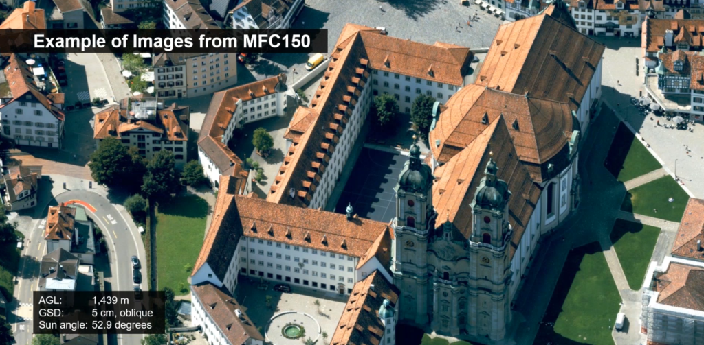
With two configurations for camera focal lengths – CityMapper-2S(tandard) and CityMapper-2H(igh) – you can develop personalised flights plans to satisfy higher or lower flying height requirements. The Leica MFC150 and MFC150-NIR cameras use CMOS technology and are equipped with Leica Geosystems’ unique Forward Motion Compensation (FMC) technology, allowing the capture of high-quality imagery even in difficult lighting conditions requiring longer exposures with no reduction in efficiency. The camera focal lengths used for CityMapper-2S are 112 millimetres RGB nadir, 70 mm NIR nadir and 146 mm RGB oblique while the camera focal lengths for CityMapper-2H are 146 mm RGB nadir, 70 mm NIR nadir and 189 mm RGB oblique.
The Hyperion2+ LiDAR unit, derived from the same linear-mode LiDAR found in the Leica TerrainMapper, enables flights from 300-5,500 metres Above Ground Level (AGL) with up to 2 Megahertz pulse rate. The sensor can accommodate up to 15 returns per outbound laser pulse with a minimum return separation of less than 50 centimetres. The technology features gateless Multiple Pulses in the Air (MPiA), enabling the collection of point clouds in the most complex reliefs and urban spaces. Handling up to 35 MPiA zones simultaneously, the CityMapper-2 deals with MPiA zone ambiguity even when returns come from surfaces in non-consecutive MPiA zones.
The CityMapper-2 also features a constant density mode allowing 35% lower data rates than when using constant Pulse Repetition Frequency (PRF), resulting in more even point distribution and more consistent classification filter performance. Nadir GSD (Ground Sample Distance) capture starts at 2 cm at a typical minimum flying height of around 500 m and increases to 10 cm at a typical maximum flying height of around 3,000 m with point densities of 50 points/m2 to 4 points/m2, respectively. An 80% forward overlap at just 2 cm Nadir GSD with a typical minimum ground speed of 100 knots can be achieved with the CityMapper-2. Finally, a defining aspect of high-quality LiDAR data capture is a Smooth Surface Repeatability (RMSDz). At less than 3 cm RMSDz, the CityMapper-2 can maintain 2,000 kHz up to about 1,500 m flying height. At less than 6 cm RMSDz, the same 2,000 kHz can be maintained up to about 2,000 m flying height and both Smooth Surface Repeatability specifications can be met at even higher flying heights at lower pulse rates.
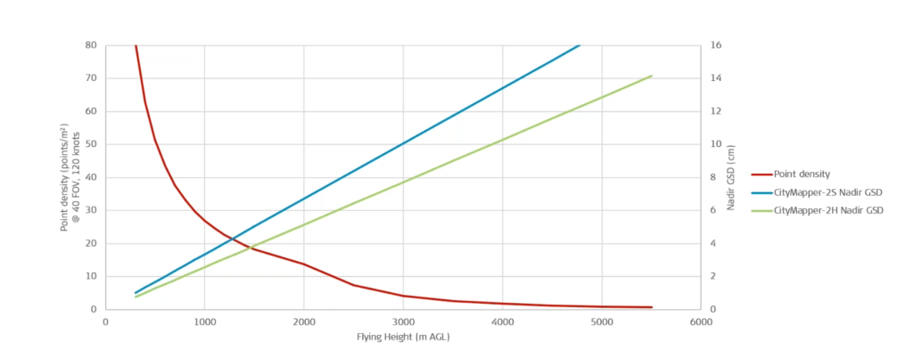
Point Density and Nadir GSD versus Flying Height
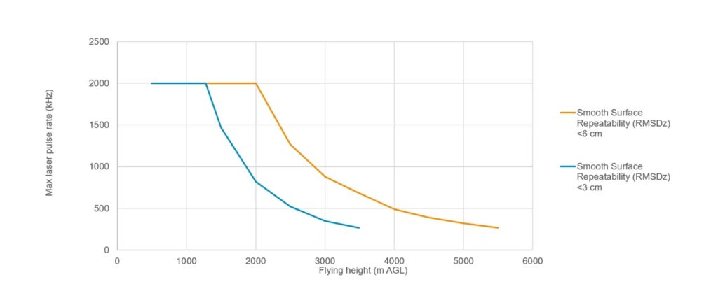
Smooth Surface Repeatability
With these upgraded features come new flight planning optimisation parameters. To plan the most effective project with the CityMapper-2, Leica MissionPro software is required. This advanced 3D airborne mission planning software provides global views with multiple features to develop flights plans with increased efficiency and productivity.
Three key parameters to consider in planning for the CityMapper-2 project are Area of Interest (AOI), stereo coverage safety factor and data volume, as described below:
- AOI Comparison
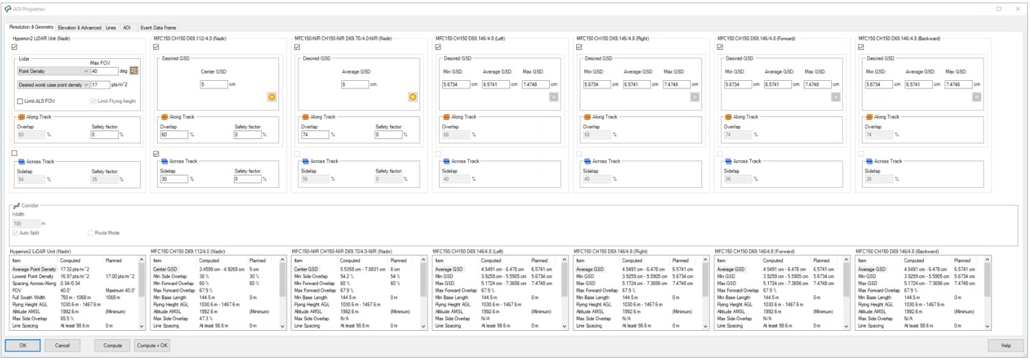
In the Resolution & Geometry tab of MissionPro, the Area of Interest (AOI) Properties show all seven sensors (six cameras and one LiDAR unit) in the CityMapper-2 together to compare to each other. You can view the point density and field of view (FOV) for the LiDAR unit, and the GSD, Along Track Overlap (base length) and Across Track Sidelap (flight line spacing) for the imaging sensors. A 60% value for the base length and a 30% imaging side overlap are the standard photogrammertic values and is recommended dependent upon the application. Once the GSD is entered, the software automatically calculates all other values for the system. A typical nadir 5 cm GSD will usually result in an oblique 6.5 cm GSD for CityMapper-2S.
- Safety Factor
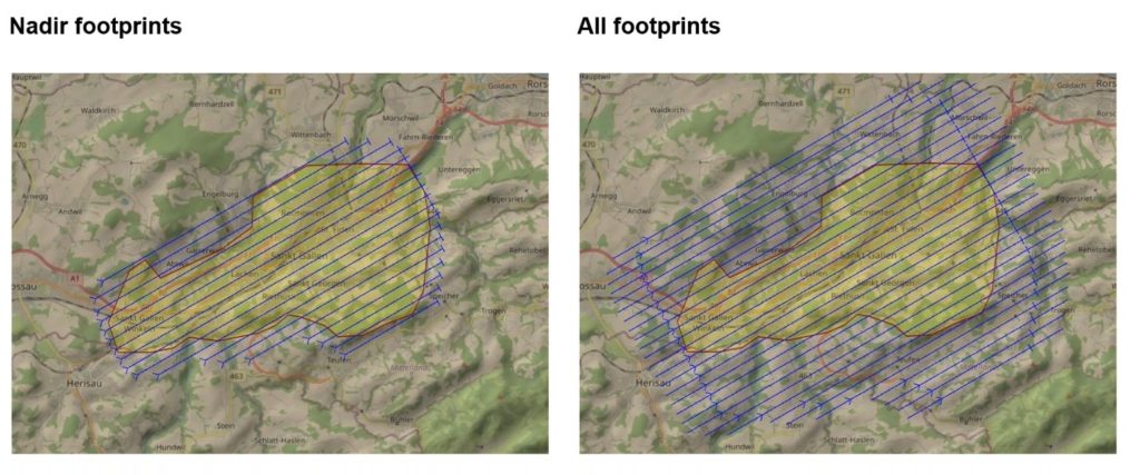
In the Elevation & Advanced Properties tab of MissionPro, it’s important to note the Safety Factor option of Nadir footprints or All footprints. The default option for flight planning with oblique cameras is All footprints. The flight plan will be calculated for every sensor to capture stereoscopic coverage in the AOI, increasing the number and length of flight lines. This option should be used when complete stereo coverage of the entire AOI is necessary on both nadir and oblique cameras. In the other Nadir footprint option, only the nadir sensors will capture complete stereoscopic coverage inside the AOI. This lessens the number and length of the flight lines and should be used when the AOI is larger than the area needed for oblique image coverage. The oblique footprint offset for the CityMapper-2H is larger than on the CityMapper-2S, and will increase length and number of flight lines over that in a CityMapper-2S flight plan.
- Data Estimation
Depending on the project, the CityMapper-2 will produce a variable amount of data per flight line. As a baseline, roughly 725 MB of image data will be captured per event. This value, of course, also depends on how the image content and resulting compression affects the output image size. For LiDAR, the estimate is affected by PRF, number of returns, and the Waveform Data (WFD) setting (if waveform data recording is enabled). The chart below provides a rough baseline:
|
PRF (kHz) |
Number of returns | Data rate (MiB/second) |
| 2,000 | 15 | 200* |
| 1,500 | 15 | 150* |
| 1,000 | 15 | 100* |
*1 Megabyte (MiB) = 10242 bytes
To process the data, the Leica HxMap unified high-performance multi-sensor workflow platform is required.
CityMapper-2 offers an advanced means to create 3D digital twins of cities, digitalising the world we live in and enabling the production of the most detailed geospatial base layers. With these upgraded features and tips on planning your next CityMapper-2 project, the possibilities are boundless.
To learn more about planning your next CityMapper-2 project, watch the webinar with a full project demonstration How to plan for a Leica CityMapper-2 project here.

With more than a decade of experience in airborne mission software development, Jacques Markram is the product manager for Leica MissionPro and FlightPro.